The header for the DBPRO expansion cable is found on the side face.

Rear I/O of the ZxR main body
In order we can find 6.3mm microphone jack, 6.3mm headphone hack, RCA L&R, Rear L/R 3.5mm jack, Centre/Sub 3.5mm jack. Who doesn't like gold?

The ZxR Bare
On removing the EMI shield we find a neat array of capacitors and chips, an additional copper EMI shield separated the analogue circuitry from the digital circuitry.

Rows of polyester film capacitors
At the back end, we can find 16 NTE polyester film capacitors, with a few exceptions, high grade 'Fine Gold' Nichicon capacitors are used everywhere else.

Around the headphone circuitry
The three large white plastic boxes are micro relays, this is likely used switch between the headphone and speakers on the fly via the software drivers. In this area we also find 4 removable opamps (operational amplifiers) 2x LME 49710NA and 2x JRC 2114D. On the far right you can find the TPA6120A2 headphone amplifier.

A closer look at some more SMDs
In the middle area we can see a line of four JRC 2114 opamps, these are soldered on so would be fairly difficult to replace should one seek to modify the sound card beyond the removable opamps.

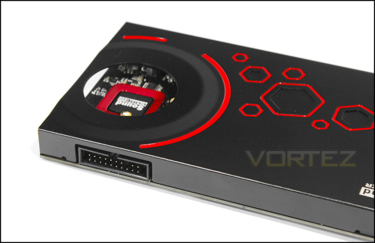
The Sound Core3D audio processor
The Sound Core3D is fairly prominent in this image though, looking closely along the copper EMI shield, there are two PCM 1798 DACs and a single PCM 1794 DAC used for the primary stereo channels, all of which have a resolution of 24bits and a sample rate of 192kHz.

A digital audio receiver
The Cirrus 8416CN is used as a high quality digital audio receiver which supports sample rates of up to 192kHz.

Creative CA0113-4AG HDA bus controller can be seen in the mid left


