
Disclaimer: Before we proceed with any instructions or information, we need to make it perfectly clear that this will void any warranty your CPU currently has, and there is a risk involved. You may end up with a dead CPU if you try this yourself. This applies to Intel, AMD and any other manufacturers. We do not endorse any action you take on your own processor.
In the past, professional overclockers and the like would remove the lid from their prized processor using razor blades and brute force; this was incredibly risky, both to the CPU and the offender’s hands. 8Pack worked alongside Roman Harthung, also known as Der8auer, to design and produce a de-lidding tool - Der8auer is a talented overclocker who works at OcUK's sister company, CaseKing in Germany. CaseKing holds the global patent on this range of de-lidding tools.
Obviously, no two ranges of CPUs are the same, with small differences to the IHS and PCB, so each range of CPUs needs a separate tool. Luckily for us, Intel have retained their design from Skylake through to the most recent Coffee Lake, with Kaby Lake in-between; this meant that no re-design was needed for the previous 3 generations of 1156 socket CPUs from Intel.
To begin the process of removing the IHS, you must first align the CPU within the base of the de-lidding tool, ensuring the PCB is held firmly in place.

The second step is marrying the lid with the base, ensuring all four screw holes line up, then tightening in sequence to prevent the CPU from moving within the jig.
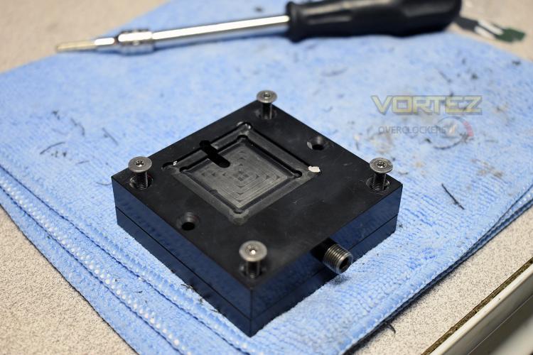
Once your CPU is entombed within its acrylic chamber, it’s time to pop the IHS off the PBC. This is, by a long way, the scariest moment of the entire procedure. To remove the IHS, the hex-holt at the bottom is slowly turned until pressure builds against the side of the heatspreader. Eventually, after a few moments of worry, there’s a terrifying crack as the Intel-applied glue is broken.
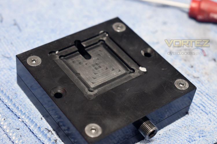
After releasing the processor, it was evident that the procedure had worked with the gasket being visible and the heatspreader now lying loose on top.
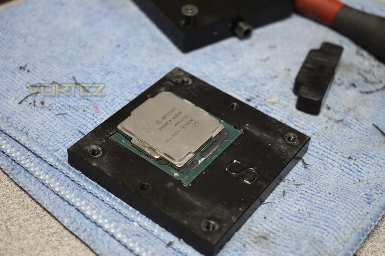
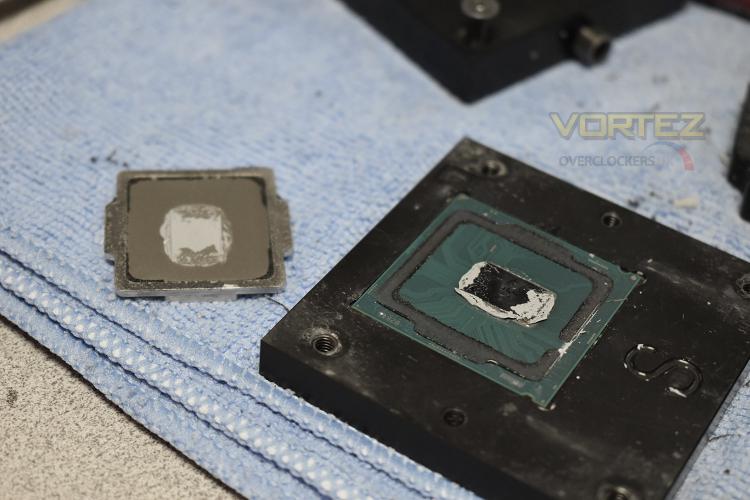
Now the delicate procedure begins – removing the glue and Thermal Interface Material. The TIM is removed using pure alcohol and a lint free cloth, then a high grade scouring pad, to ensure that any residue is taken away and to prepare the surface for the liquid metal, this practice is done with extreme care and the full attention of the technician. The gasket was removed using the fingernail – the dexterity required to remove the glue without damaging the PCB is only reliably possible with this method.
In the past, professional overclockers and the like would remove the lid from their prized processor using razor blades and brute force; this was incredibly risky, both to the CPU and the offender’s hands. 8Pack worked alongside Roman Harthung, also known as Der8auer, to design and produce a de-lidding tool - Der8auer is a talented overclocker who works at OcUK's sister company, CaseKing in Germany. CaseKing holds the global patent on this range of de-lidding tools.
Obviously, no two ranges of CPUs are the same, with small differences to the IHS and PCB, so each range of CPUs needs a separate tool. Luckily for us, Intel have retained their design from Skylake through to the most recent Coffee Lake, with Kaby Lake in-between; this meant that no re-design was needed for the previous 3 generations of 1156 socket CPUs from Intel.
To begin the process of removing the IHS, you must first align the CPU within the base of the de-lidding tool, ensuring the PCB is held firmly in place.
The second step is marrying the lid with the base, ensuring all four screw holes line up, then tightening in sequence to prevent the CPU from moving within the jig.
Once your CPU is entombed within its acrylic chamber, it’s time to pop the IHS off the PBC. This is, by a long way, the scariest moment of the entire procedure. To remove the IHS, the hex-holt at the bottom is slowly turned until pressure builds against the side of the heatspreader. Eventually, after a few moments of worry, there’s a terrifying crack as the Intel-applied glue is broken.
After releasing the processor, it was evident that the procedure had worked with the gasket being visible and the heatspreader now lying loose on top.
Now the delicate procedure begins – removing the glue and Thermal Interface Material. The TIM is removed using pure alcohol and a lint free cloth, then a high grade scouring pad, to ensure that any residue is taken away and to prepare the surface for the liquid metal, this practice is done with extreme care and the full attention of the technician. The gasket was removed using the fingernail – the dexterity required to remove the glue without damaging the PCB is only reliably possible with this method.


